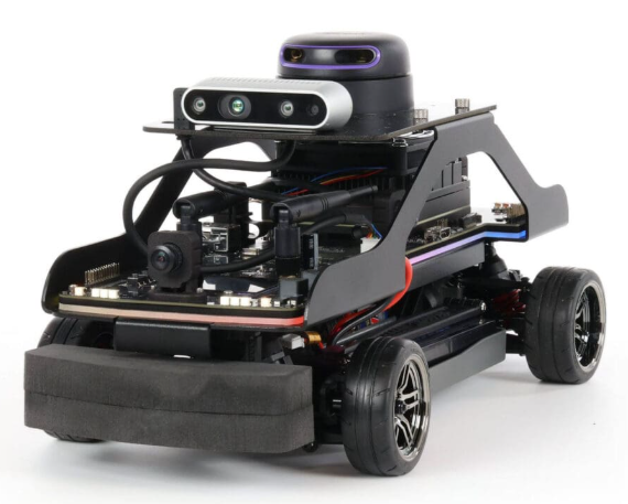
Appearance
2. QCar 2
1. Overview
Information on Quanser: https://www.quanser.com/products/qcar-2
The QCar 2 is the feature vehicle of the Self-Driving Car Studio, an open-architecture, 1/10th scale vehicle designed for academic self-driving initiatives. Driven by the powerful NVIDIA Orin AGX and equipped with a comprehensive suite of inertial, visual, and ranging sensors, it is designed to elevate your research, education, and outreach to the next level.
2. Quick Start Guide
2.1 Setup QCar 2
Use QCar 2 Quick Start Guide for instructions about installing the batteries.
2.2 IP Addresses
- QCar 2 A: 192.168.2.209
- QCar 2 B: 192.168.2.162
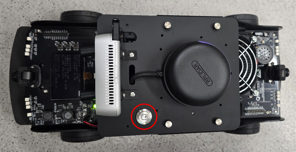
2.3 On/Off Button
On/Off button does not match the manual. Shown in the red circle below:
2.4 Install Quick Start Application
If the Quick Start Application is not running on the QCar 2 as shown in the manual:
Make sure QCar 2 is turned on.
Find the Quanser "Monitor App" icon in the system tray (top right in image):
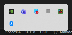
Click on the Monitor App icon.
Select "Target > Remote..." and set "Target URI" to match address shown on QCar 2:
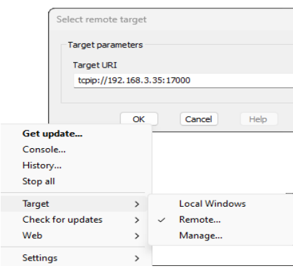
- Select "Target > Manage..." and make sure "URI" is set to QCar 2.
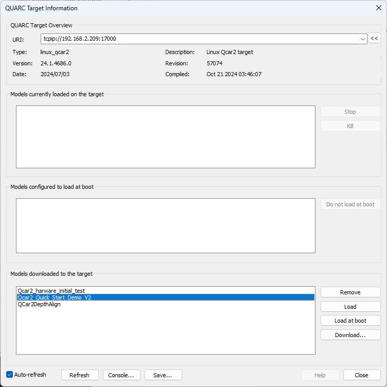
If you do not see "Qcar2_Quick_Start_Demo_V2" in "Models downloaded", click on "Download..." and select "QCar2_Quick_Start_Demo_V2.rt-linux_qcar2" from "Quanser > 2_quick_start_guide > qcar2 > hardware".
Select "Qcar2_Quick_Start_Demo_V2" and select "Load at boot" and Close.
Reboot the QCar 2.
3. User Manuals
The full QCar 2 User Manuals can be found at QCar 2 User Manuals.
4. Connectivity
4.1 Ping QCar 2
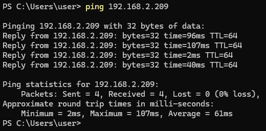
To check that the QCar is reachable from the GCS, ping using the QCar 2's IP address. For example:
bash
ping 192.168.2.209Example output:
4.2 SSH to QCar 2
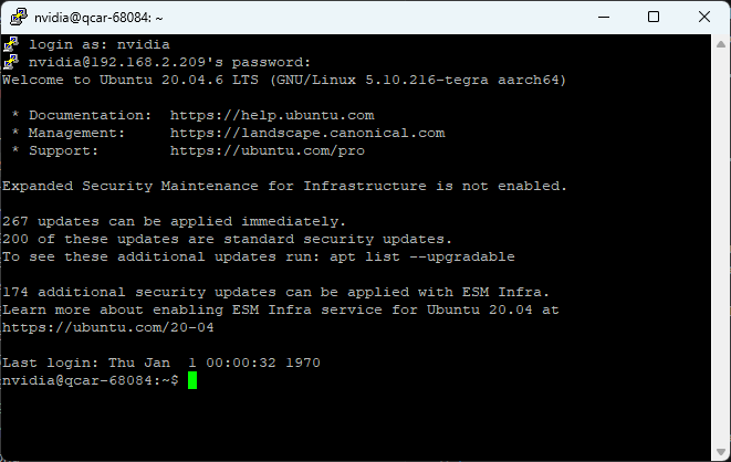
- To SSH into the QCar 2, use
putty, specifying the IP address of the QCar 2:
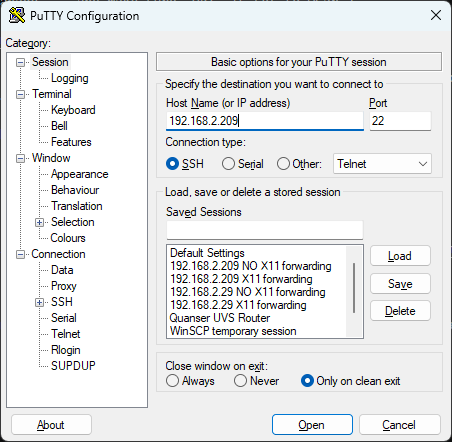
- Use login
nvidiaand passwordnvidia:
4.3 Transferring Files
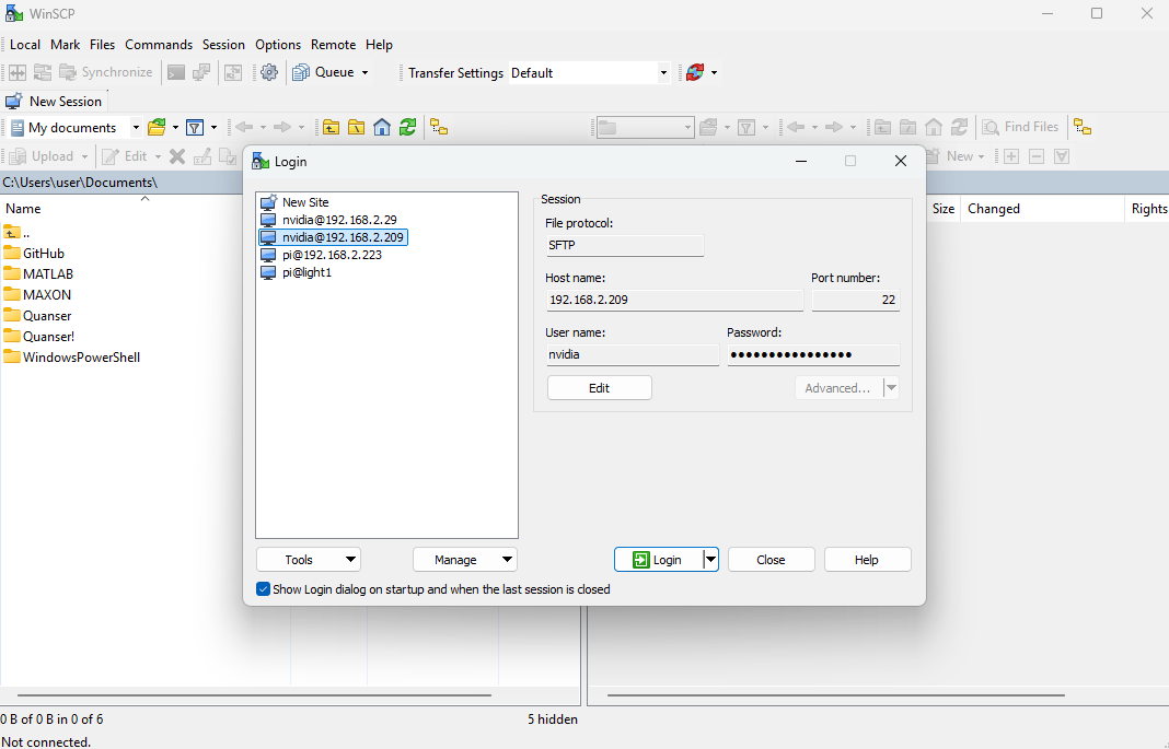
To transfer files to and from the QCar 2, you can use WinSCP:
- Specify the IP address of the QCar 2
- User name:
nvidia - Password:
nvidia:
4.4 Windows Remote Desktop
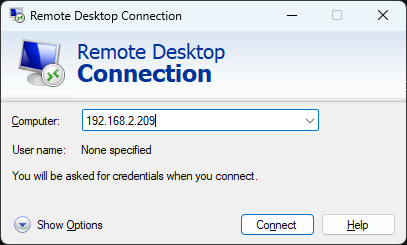
- Open
Remote Desktop Applicationon the GCS and enter the QCar 2 IP address, for example:
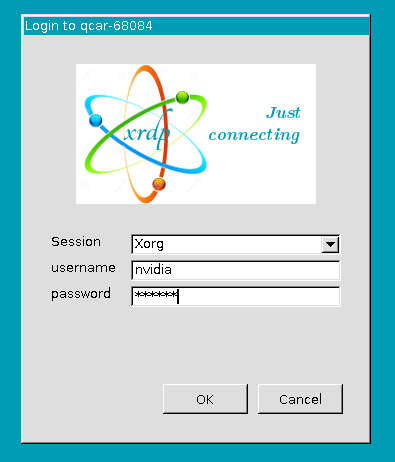
- In the login dialog, use username
nvidiaand passwordnvidia:
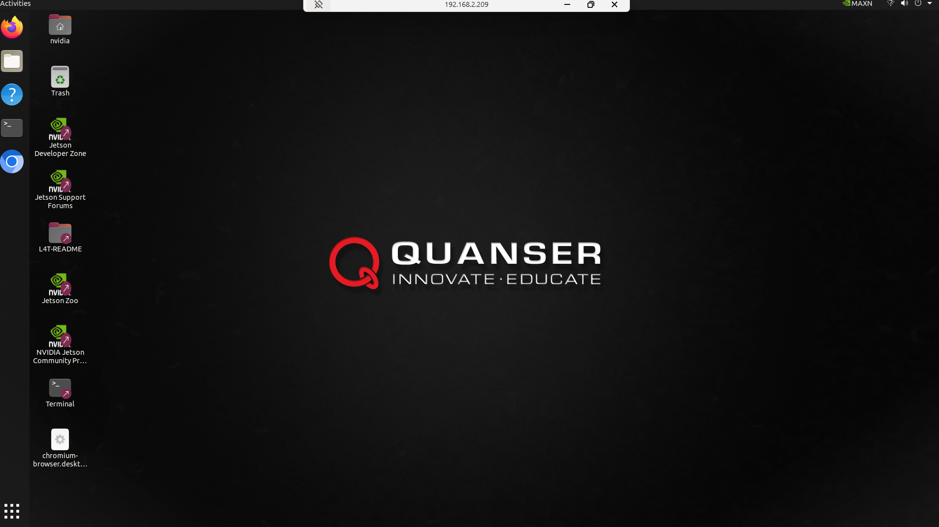
- Should show the QCar 2 desktop:
4.5 VcXsrv/XLaunch
If your code creates any graphical output such as cv2 display windows, an X11 server can be used. The advantage of the X11 interface is that it can be connected to the QCar 2 from a cold boot.
A PuTTY terminal can be used to provide X11 forwarding but a display server must be present on the GCS. A tool - VcXsrv (under the name XLaunch in the start menu), has been installed on the GCS by default for this purpose.
Launch
XLaunch.Pass through all four tabs with default options:
- Multiple windows
- Start no client
- Clipboard and Native opengl
- Finish
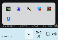
- An XLaunch display server should now be visible in your toolbar (the
Xshown below):
- Launch
PuTTY.
- Enter the IP address of the QCar 2
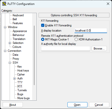
- Navigate to the
Connection > SSH > X11tab andEnable X11 forwarding - Enter
localhost:0.0in theX display location
- Click
Open
Login (username
nvidia, and passwordnvidia),Enter the following command to check the display server:
bash
echo $DISPLAYShould show something similar to:
text
nvidia@qcar-68084:~$ echo $DISPLAY
localhost:10.0- Type in test command:
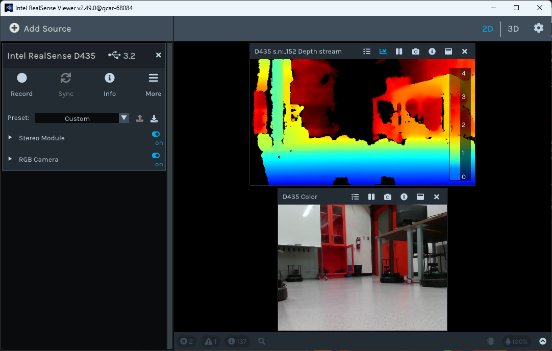
bash
realsense-viewerThe viewer application from the QCar 2 should display on your GCS display server in Windows. Turn on the Stereo Module, RGB Camera, and 2D:
5. System Hardware
The QCar 2 System Hardware is documented in the linked PDF file:
6. Python Software
Information about designing Python applications for the QCar 2 is documented in the linked PDF file:
- Display the version of
pythonusing the following (should be3.8.10):
bash
python3 --version- To see the Python packages installed using
pip:
bash
python3 -m pip list6.1 Application Modules Setup
The Quanser Python libraries for the QCar 2 include:
High-Level Application Libraries (
hal). Thehallibrary includes higher-level Python libraries, equipped with a list of Python functions commonly used throughout the Quanser provided content.Python Application Libraries (
pal). Thepallibrary is a Python application library which makes use of the Quanser Modules. These are intended to give users the ability to interface with hardware on the QCar 2.
To be able to run the provided examples for QCar 2, these Python libraries need to be transferred to the car:
On the QCar 2, create directory
/home/nvidia/Documents/Quanserif necessary.Using
WinSCP, copy0_libraries,5_research, and6_teachingfrom the GCS to the QCar 2.Edit
~/.bashrcon the QCar 2 and set:
bash
export PYTHONPATH=$PYTHONPATH:/home/nvidia/Documents/Quanser/0_libraries/python
export QAL_DIR=/home/nvidia/Documents/Quanser
6.2 Developing QCar 2 Applications
For QCar 2, it is recommended to connect to the QCar remotely via Remote Desktop and develop directly on the QCar using VS code.
However, it is not pre-installed in the QCar. To check if installed:
bash
codeIf it needs to be installed:
Download the Debian package from Visual Studio Code, and select the “Arm64” option of the Debian package.
To install:
bash
sudo apt install ./<file>.deb7. Python Hardware Tests
Overview document QCar2_Hardware Test.pdf
Go to appropriate directory:
bash
cd /home/nvidia/Documents/Quanser/5_research/sdcs/qcar2/hardware/hardware_tests7.1 Intel Realsense Camera
Run:
bash
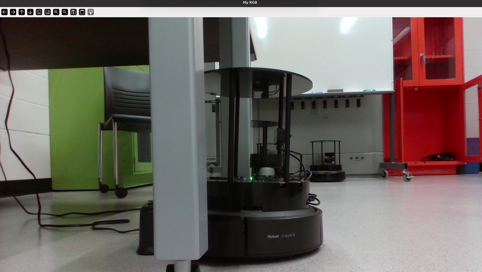
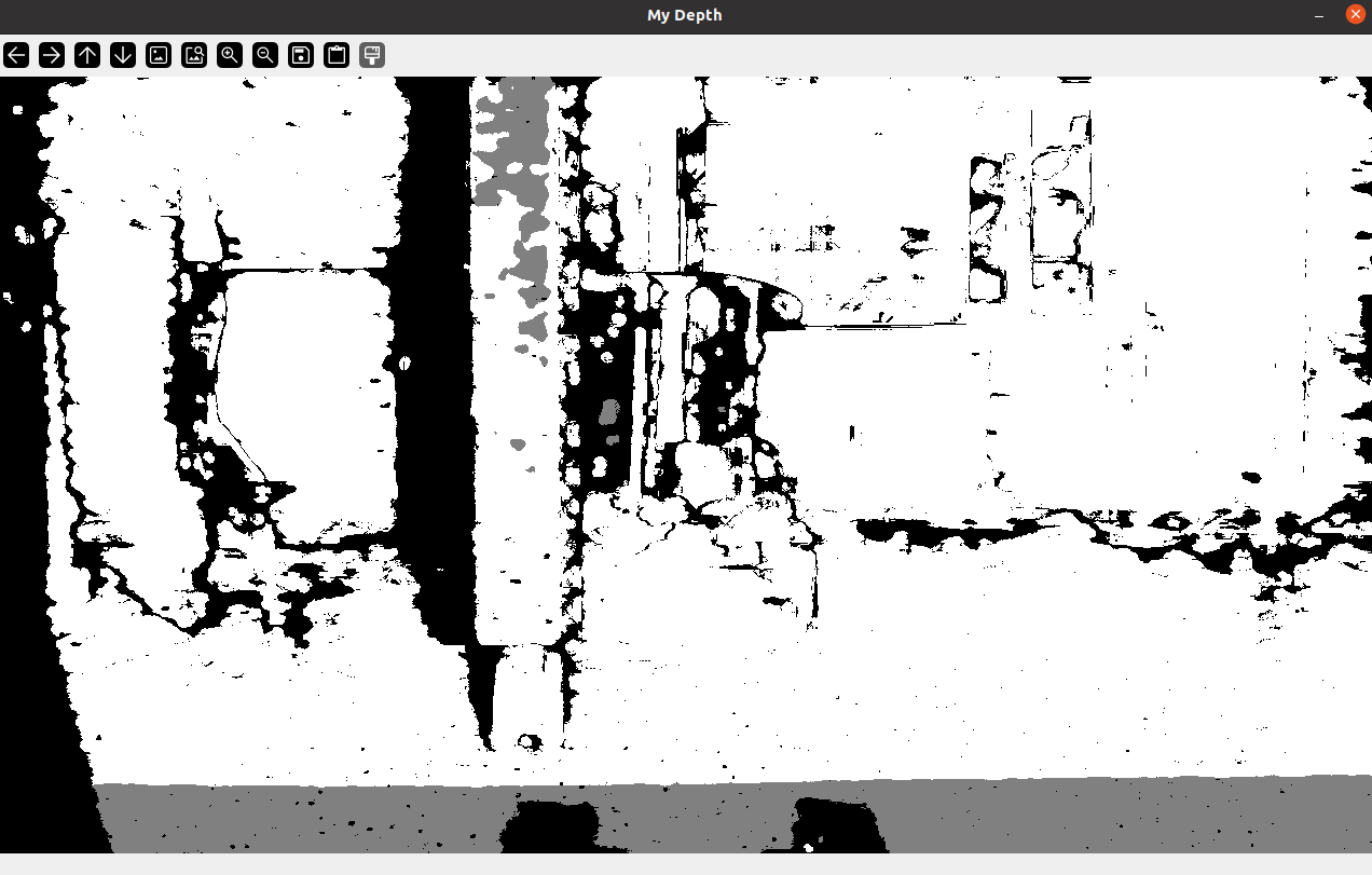
python3 QCar2_hardware_test_intelrealsense.pyThis script should launch an RGB and a Depth window on your screen. An example output is shown below (RGB and Depth). Note that it automatically times out after about 30 seconds and exits the script.
Example RGB image:
Example Depth image:
Script content:
python
'''hardware_test_intelrealsense.py

This example demonstrates how to read and display depth & RGB image data
from the Intel Realsense camera.
'''
import time
import cv2
from pal.products.qcar import QCarRealSense, IS_PHYSICAL_QCAR

if not IS_PHYSICAL_QCAR:
    import qlabs_setup
    qlabs_setup.setup()


#Initial Setup
runTime = 30.0 # seconds
max_distance = 2 # meters (for depth camera)

with QCarRealSense(mode='RGB, Depth') as myCam:
    t0 = time.time()
    while time.time() - t0 < runTime:

        myCam.read_RGB()
        cv2.imshow('My RGB', myCam.imageBufferRGB)

        myCam.read_depth(dataMode='PX')
        cv2.imshow('My Depth', myCam.imageBufferDepthPX/max_distance)

cv2.waitKey(100)7.2 Polar Plot of LIDAR
Run:
bash
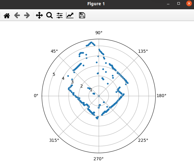
python3 QCar2_hardware_test_rp_lidar_a2.pyThis application should display a polar plot of the LIDAR scans. A sample output is shown here. Note that the 0-degree mark corresponds to the front of the vehicle, and the data is scanned in a counterclockwise positive direction.
Script content:
python
'''This example demonstrates how to read and display data from the QCar Lidar
'''
import time
import matplotlib.pyplot as plt
from pal.products.qcar import QCarLidar
# from pal.utilities.lidar import Lidar

# polar plot object for displaying LIDAR data later on
ax = plt.subplot(111, projection='polar')
plt.show(block=False)

runTime = 10.0 # seconds
# Lidar settings
numMeasurements 	 = 1000	# Points
lidarMeasurementMode 	 = 2
lidarInterpolationMode = 0

# LIDAR initialization and measurement buffers
myLidar = QCarLidar(
	numMeasurements=numMeasurements,
	rangingDistanceMode=lidarMeasurementMode,
	interpolationMode=lidarInterpolationMode
)


t0 = time.time()
while time.time() - t0  < runTime:
    plt.cla()

    # Capture LIDAR data
    myLidar.read()

    ax.scatter(myLidar.angles, myLidar.distances, marker='.')
    ax.set_theta_zero_location("W")
    ax.set_theta_direction(-1)

    plt.pause(0.1)

myLidar.terminate()7.3 Basic I/O
Run:
bash
python3 QCar2_hardware_test_basic_io.pyThis script should automatically drive a sinusoidal throttle and steering command to the wheels. As the steering changes left and right, the corresponding LED indicators should light up. As the wheels spin forward or backwards, the corresponding headlamps or rear lamps/reverse indicators should light up.
Example terminal output:
text
time: 5.00, Battery Voltage: 11.65, Motor Current: 0.36, Motor Encoder: [-12393], Motor Tach: 0.23, Accelerometer: [0.19153613 0.1436521 9.63426748], Gyroscope: [0.00918791 0.01105212 0.24181503]Script content:
python
'''hardware_test_basic_io.py

This example demonstrates how to use the QCar class to perform basic I/O.
Learn how to write throttle and steering, as well as LED commands to the
vehicle, and read sensor data such as battery voltage. See the QCar class
definition for other sensor buffers such as motorTach, accelometer, gyroscope
etc.
'''
import numpy as np
import time
from pal.products.qcar import QCar, IS_PHYSICAL_QCAR

if not IS_PHYSICAL_QCAR:
    import qlabs_setup
    qlabs_setup.setup()


#Initial Setup
sampleRate = 200
runTime = 5.0 # seconds

with QCar(readMode=1, frequency=sampleRate) as myCar:
    t0 = time.time()
    while time.time() - t0  < runTime:
        t = time.time()

        # Read from onboard sensors
        myCar.read()

        # Basic IO - write motor commands
        throttle = 0.1 * np.sin(t*2*np.pi/5)
        steering = 0.3 * np.sin(t*2*np.pi/2.5)

        LEDs = np.array([0, 0, 0, 0, 0, 0, 1, 1])
        if steering > 0.15:
            LEDs[0] = 1
            LEDs[2] = 1
        elif steering < -0.15:
            LEDs[1] = 1
            LEDs[3] = 1
        if throttle < 0:
            LEDs[5] = 1

        myCar.write(throttle, steering, LEDs)

        print(
            f'time: {(t-t0):.2f}'
            + f', Battery Voltage: {myCar.batteryVoltage:.2f}'
            + f', Motor Current: {myCar.motorCurrent:.2f}'
            + f', Motor Encoder: {myCar.motorEncoder}'
            + f', Motor Tach: {myCar.motorTach:.2f}'
            + f', Accelerometer: {myCar.accelerometer}'
            + f', Gyroscope: {myCar.gyroscope}'
)7.4 Gamepad
Run:
bash
python3 QCar2_hardware_test_gamepad.pyThis script initializes and reads the Joystick - Logitech Gamepad F710. Plug the gamepad’s USB dongle into the USB ports on the QCar 2. As you operate the joystick, the status of corresponding buttons will be printed in the terminal.
Example terminal output:
text
Left Laterial:		-0.00
Left Longitudonal:	-0.00
Trigger:		    0.00
Right Lateral:		0.00
Right Longitudonal:	0.00
Button A:		    0
Button B:		    0
Button X:		    0
Button Y:		    0
Button LB:		    0
Button RB:		    0
Up:			        0
Right:			    0
Down:			    0
Left:			    0
Script content (Note: On line 36, use clear for Linux, default was cls which is for Windows):
python
'''hardware_test_gamepad.py

This example demonstrates how to read data from the Logitech F710 gamepad.
The data received from buttons independently might change depending on the OS
(windows vs. linux)
'''
from pal.utilities.gamepad import LogitechF710
import time
import os


# Timing and Initialization
startTime = time.time()
def elapsed_time():
    return time.time() - startTime

simulationTime = 60
sampleRate = 100
sampleTime = 1/sampleRate
gpad = LogitechF710()

# Restart starTime just before Main Loop
startTime = time.time()

## Main Loop
try:
    while elapsed_time() < simulationTime:
        # Start timing this iteration
        start = elapsed_time()

        # Basic IO - write motor commands
        new = gpad.read()

        if new:
            # Clear the Screen for better readability
            os.system('clear')

            # Print out the gamepad IO read
            print("Left Laterial:\t\t{0:.2f}\nLeft Longitudonal:\t{1:.2f}\nTrigger:\t\t{2:.2f}\nRight Lateral:\t\t{3:.2f}\nRight Longitudonal:\t{4:.2f}"
                .format(gpad.leftJoystickX, gpad.leftJoystickY, gpad.trigger, gpad.rightJoystickX, gpad.rightJoystickY))
            print("Button A:\t\t{0:.0f}\nButton B:\t\t{1:.0f}\nButton X:\t\t{2:.0f}\nButton Y:\t\t{3:.0f}\nButton LB:\t\t{4:.0f}\nButton RB:\t\t{5:.0f}"
                .format(gpad.buttonA, gpad.buttonB, gpad.buttonX, gpad.buttonY, gpad.buttonLeft, gpad.buttonRight))
            print("Up:\t\t\t{0:.0f}\nRight:\t\t\t{1:.0f}\nDown:\t\t\t{2:.0f}\nLeft:\t\t\t{3:.0f}"
                .format(gpad.up, gpad.right, gpad.down, gpad.left))

        # End timing this iteration
        end = elapsed_time()

        # Calculate computation time, and the time that the thread should
        # pause/sleep for
        computation_time = end - start
        sleep_time = sampleTime - computation_time%sampleTime

        # Pause/sleep and print out the current timestamp
        time.sleep(sleep_time)

except KeyboardInterrupt:
    print("User interrupted!")

finally:
    # Terminate Joystick properly
gpad.terminate()7.5 CSI Cameras
CSI camera remote streaming currently does not support Windows Remote Desktop or X11 forwarding. Make sure you are not running Windows Remote Desktop when you run the probe.
To see the CSI feeds remotely:
Modify
QCar2_hardware_test_csi_cameras_probe.pyon the QCar 2 and change the variableipObserverin the “Initial Setup” section to the IP of the GCS (i.e.,192.168.2.100).Run
observeron GCS:
bash
python QCar2_hardware_test_csi_cameras_observer.pyputtyinto the QCar 2 (without X11 forwarding) and runprobe(Note: default 30 second runtime before terminating):
bash
python3 QCar2_hardware_test_csi_cameras_probe.pyOn the GCS, four windows should open showing the images from the four cameras. When the probe times out and terminates, the observer will terminate.
8. Applications
8.1 Manula Drive
Documentation Manual Drive.pdf
- On the QCar 2, change directory to:
bash
cd /home/nvidia/Documents/Quanser/5_research/sdcs/qcar2/hardware/applications/manual_drive- Run:
bash
python3 QCar2_task_manual_drive.py- Use the controller:
- Make sure front
X | Oswitch on controller is in theOposition - Make sure the
Modelight is off - Hold down the
LBbutton - Use
Left Stickfor steering (sideways) - Use
RTfor throttle (normally forward) - To reverse, hold down
Abutton and useRT
- Code for
QCar2_task_manual_drive.py:
python
## task_task_manual_drive.py
# This example demonstrates how to use the LogitechF710 to send throttle and steering
# commands to the QCar depending on 2 driving styles.
# Use the hardware_test_basic_io.py to troubleshoot uses trying to drive the QCar.

from pal.products.qcar import QCar
from pal.utilities.gamepad import LogitechF710
from pal.utilities.math import *

import os
import time
import struct
import numpy as np

# -- -- -- -- -- -- -- -- -- -- -- -- -- -- -- -- -- -- -- -- -- -- -- -- -- -- -- -- -- -- -- -- -- -- -- --
## Timing Parameters and methods
startTime = time.time()
def elapsed_time():
    return time.time() - startTime

sampleRate     = 50
sampleTime     = 1/sampleRate
simulationTime = 60.0
print('Sample Time: ', sampleTime)

# Additional parameters
counter = 0

# Initialize motor command array
QCarCommand = np.array([0,0])

# Set up a differentiator to get encoderSpeed from encoderCounts
diff = Calculus().differentiator_variable(sampleTime)
_ = next(diff)
timeStep = sampleTime

# -- -- -- -- -- -- -- -- -- -- -- -- -- -- -- -- -- -- -- -- -- -- -- -- -- -- -- -- -- -- -- -- -- -- -- --
## QCar and Gamepad Initialization
# Changing readmode to 0 to use imediate I/O
readMode = 0

myCar = QCar(readMode=readMode)
gpad = LogitechF710()

# -- -- -- -- -- -- -- -- -- -- -- -- -- -- -- -- -- -- -- -- -- -- -- -- -- -- -- -- -- -- -- -- -- -- -- --
## Driving Configuration: Use 3 toggles or 4 toggles mode as you see fit:
# Common to both 3 or 4 mode
#   Steering                    - Left Lateral axis
#   Arm                         - buttonLeft
# In 3 mode:
#   Throttle (Drive or Reverse) - Right Longitudonal axis
# In 4 mode:
#   Throttle                    - Right Trigger (always positive)
#   Button A                    - Reverse if held, Drive otherwise
configuration = '4' # change to '4' if required

# -- -- -- -- -- -- -- -- -- -- -- -- -- -- -- -- -- -- -- -- -- -- -- -- -- -- -- -- -- -- -- -- -- -- -- --
# Reset startTime before Main Loop
startTime = time.time()

## Main Loop
try:
    while elapsed_time() < simulationTime:
        # Start timing this iteration
        start = elapsed_time()

        # Read Gamepad states
        new = gpad.read()

        # Basic IO - write motor commands
        if configuration == '3':
            if new and gpad.buttonLeft:
                QCarCommand = np.array([0.3*gpad.rightJoystickY, 0.5*gpad.leftJoystickX])
        elif configuration == '4':
            if new and gpad.buttonLeft:
                if gpad.buttonA:
                    QCarCommand = np.array([-0.3*gpad.trigger, 0.5*gpad.leftJoystickX])
                else:
                    QCarCommand = np.array([0.3*gpad.trigger, 0.5*gpad.leftJoystickX])

        LEDs = np.array([0, 0, 0, 0, 0, 0, 1, 1])

        # Adjust LED indicators based on steering and reverse indicators based on reverse gear
        if QCarCommand[1] > 0.3:
            LEDs[0] = 1
            LEDs[2] = 1
        elif QCarCommand[1] < -0.3:
            LEDs[1] = 1
            LEDs[3] = 1
        if QCarCommand[0] < 0:
            LEDs[5] = 1

        # Perform I/O
        myCar.read_write_std(throttle= QCarCommand[0],
                             steering= QCarCommand[1],
							 LEDs= LEDs)

        batteryVoltage = myCar.batteryVoltage

        # Estimate linear speed in m/s
        linearSpeed   = myCar.motorTach
        # encoderSpeed  = myCar.motorTach/myCar.CPS_TO_MPS
        # End timing this iteration
        end = elapsed_time()

        # Calculate computation time, and the time that the thread should pause/sleep for
        computationTime = end - start
        sleepTime = sampleTime - computationTime%sampleTime

        # Pause/sleep and print out the current timestamp
        time.sleep(sleepTime)

        if new:
            os.system('cls' if os.name == 'nt' else 'clear')
            print("Car Speed:\t\t\t{0:1.2f}\tm/s\nRemaining battery capacity:\t{1:4.2f}\t%\nMotor throttle:\t\t\t{2:4.2f}\t% PWM\nSteering:\t\t\t{3:3.2f}\trad"
                                                            .format(linearSpeed, 100 - (batteryVoltage - 10.5)*100/(12.6 - 10.5), QCarCommand[0], QCarCommand[1]))
        timeAfterSleep = elapsed_time()
        timeStep = timeAfterSleep - start
        counter += 1

except KeyboardInterrupt:
    print("User interrupted!")

finally:
    myCar.terminate()
    gpad.terminate()
# -- -- -- -- -- -- -- -- -- -- -- -- -- -- -- -- -- -- -- -- -- -- -- -- -- -- -- -- -- -- -- -- -- -- -- --8.2 360 Vision
Documentation QCar2_360 Vision.pdf
- On the QCar 2, change directory to:
bash
cd /home/nvidia/Documents/Quanser/5_research/sdcs/qcar2/hardware/applications/360_visionModify
QCar2_imaging_360_probe.pyon the QCar 2 and change the variableipHostto the IP of the GCS (i.e.,192.168.2.100).Run
observeron GCS:
bash
cd C:\Users\user\Documents\GitHub\Quanser_Academic_Resources\5_research\sdcs\qcar2\hardware\applications\360_vision
python QCar2_imaging_360_observer.pyputtyinto the QCar 2 and runprobewithout X11 forwarding and not running Windows Remote Desktop (Note: default 60 second runtime before terminating):
bash
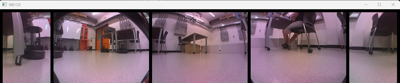
python3 QCar2_imaging_360_probe.py- On the GCS, a window should open up showing the four CSI cameras 'stitch' horizontally, example shown below. When the
probetimes out and terminates, theobservershould terminate.
- Code for
QCar2_imaging_360_probe.py:
python
## imaging_360.py
# This example demonstrates how to read all 4 csi cameras and display in a single openCV window. If you encounter any errors,
# use the hardware_test_csi_camera_single.py script to find out which camera is giving you trouble.

from pal.utilities.vision import Camera2D
from pal.utilities.probe import Probe
import time
import struct
import numpy as np

# -- -- -- -- -- -- -- -- -- -- -- -- -- -- -- -- -- -- -- -- -- -- -- -- -- -- -- -- -- -- -- -- -- -- -- --
## Timing Parameters and methods
startTime = time.time()
def elapsed_time():
    return time.time() - startTime

sampleRate     = 30.0
sampleTime     = 1/sampleRate
simulationTime = 60.0
print('Sample Time: ', sampleTime)

# -- -- -- -- -- -- -- -- -- -- -- -- -- -- -- -- -- -- -- -- -- -- -- -- -- -- -- -- -- -- -- -- -- -- -- --
# Additional parameters
ipHost, ipQCar = '192.168.3.10', 'localhost'
counter = 0
imageWidth = 640
imageHeight = 480
imageBuffer360 = np.zeros((imageHeight + 40, 4*imageWidth + 120, 3), dtype=np.uint8) # 20 px padding between pieces

# Stitch images together with black padding
horizontalBlank     = np.zeros((20, 4*imageWidth+120, 3), dtype=np.uint8)
verticalBlank       = np.zeros((imageHeight, 20, 3), dtype=np.uint8)

# -- -- -- -- -- -- -- -- -- -- -- -- -- -- -- -- -- -- -- -- -- -- -- -- -- -- -- -- -- -- -- -- -- -- -- --
## Initialize the CSI cameras and probe
myCam1 = Camera2D(cameraId="0", frameWidth=imageWidth, frameHeight=imageHeight, frameRate=sampleRate)
myCam2 = Camera2D(cameraId="1", frameWidth=imageWidth, frameHeight=imageHeight, frameRate=sampleRate)
myCam3 = Camera2D(cameraId="3", frameWidth=imageWidth, frameHeight=imageHeight, frameRate=sampleRate)
myCam4 = Camera2D(cameraId="2", frameWidth=imageWidth, frameHeight=imageHeight, frameRate=sampleRate)
probe = Probe(ip = ipHost)
probe.add_display(imageSize = [imageHeight + 40, 4*imageWidth + 120, 3], scaling = True,
                            scalingFactor= 2, name="360 CSI")

# -- -- -- -- -- -- -- -- -- -- -- -- -- -- -- -- -- -- -- -- -- -- -- -- -- -- -- -- -- -- -- -- -- -- -- --
## Main Loop
try:
    while elapsed_time() < simulationTime:
        start = time.time()
        if not probe.connected:
            probe.check_connection()
        if probe.connected:
        # Start timing this iteration

            # Capture RGB Image from CSI
            flag1=myCam1.read()
            flag2=myCam2.read()
            flag3=myCam3.read()
            flag4=myCam4.read()

            imageBuffer360 = np.concatenate(
                                            (horizontalBlank,
                                                np.concatenate((    verticalBlank,
                                                                    myCam2.imageData[:,320:640],
                                                                    verticalBlank,
                                                                    myCam3.imageData,
                                                                    verticalBlank,
                                                                    myCam4.imageData,
                                                                    verticalBlank,
                                                                    myCam1.imageData,
                                                                    verticalBlank,
                                                                    myCam2.imageData[:,0:320],
                                                                    verticalBlank),
                                                                    axis = 1),
                                                horizontalBlank
                                                ),
                                                axis=0
                                            )

            if all([flag1,flag2,flag3,flag4]): counter += 1
            if counter % 4 == 0:
                sending = probe.send(name="360 CSI",
                                    imageData=imageBuffer360)

        # End timing this iteration
        end = time.time()

        # Calculate the computation time, and the time that the thread should pause/sleep for
        computationTime = end - start
        sleepTime = sampleTime - ( computationTime % sampleTime )

        # Pause/sleep for sleepTime in milliseconds
        if sleepTime <= 0:
            sleepTime = 0
        time.sleep(sleepTime)

except KeyboardInterrupt:
    print("User interrupted!")

finally:
    # Terminate all webcam objects
    probe.terminate()
    myCam1.terminate()
    myCam2.terminate()
    myCam3.terminate()
    myCam4.terminate()
# -- -- -- -- -- -- -- -- -- -- -- -- -- -- -- -- -- -- -- -- -- -- -- -- -- -- -- -- -- -- -- -- -- -- -- --8.3 Lane Following
Documentation QCar2_Lane Following.pdf
- On the QCar 2, change directory to:
bash
cd /home/nvidia/Documents/Quanser/5_research/sdcs/qcar2/hardware/applications/lane_followingModify
QCar2_task_lane_following_probe.pyon the QCar 2 and change the variableipHostto the IP of the GCS (i.e.,192.168.2.100).Place your QCar on the right side of the yellow lane.
Run
observeron the GCS:
bash
cd C:\Users\user\Documents\GitHub\Quanser_Academic_Resources\5_research\sdcs\qcar2\hardware\applications\lane_following
python QCar2_task_lane_following_observer.pyputtyinto the QCar 2 and runprobewithout X11 forwarding and not running Windows Remote Desktop (Note: default 60 second runtime before terminating):
bash
python3 QCar2_task_lane_following_probe.py- On the GCS, a window should open up showing the colour camaera, example shown below.

The detected yellow lane is highlighted in red.
- Use the controller:
- Make sure front
X | Oswitch on controller is in theOposition - Make sure the
Modelight is off - Hold down the
LBbutton - Hold down
Xto enable automatic steering - Press
RTto provide throttle (use very light throttle)
- Code for
QCar2_task_lane_following_probe.py:
python
## task_lane_following.py
# This example combines both the left csi and motor commands to
# allow the QCar to follow a yellow lane. Use the joystick to manually drive the QCar
# to a starting position and enable the line follower by holding the X button on the LogitechF710
# To troubleshoot your camera use the hardware_test_csi_camera_single.py found in the hardware tests

# from pal.utilities.vision import Camera2D
from pal.products.qcar import QCar, QCarCameras
from pal.utilities.math import Filter
from pal.utilities.gamepad import LogitechF710
from pal.utilities.probe import Probe
from hal.utilities.image_processing import ImageProcessing

import time
import numpy as np
import cv2
import math

# -- -- -- -- -- -- -- -- -- -- -- -- -- -- -- -- -- -- -- -- -- -- -- -- -- -- -- -- -- -- -- -- -- -- -- --
## Timing Parameters and methods
sampleRate = 60
sampleTime = 1/sampleRate
print('Sample Time: ', sampleTime)

# -- -- -- -- -- -- -- -- -- -- -- -- -- -- -- -- -- -- -- -- -- -- -- -- -- -- -- -- -- -- -- -- -- -- -- --
# Additional parameters
ipHost, ipQCar = '192.168.3.10', 'localhost'
counter 	= 0
imageWidth  = 1640
imageHeight = 820
# cameraID 	= '2'

# -- -- -- -- -- -- -- -- -- -- -- -- -- -- -- -- -- -- -- -- -- -- -- -- -- -- -- -- -- -- -- -- -- -- -- --
#Setting Filter
steeringFilter = Filter().low_pass_first_order_variable(25, 0.033)
next(steeringFilter)
dt = 0.033

# -- -- -- -- -- -- -- -- -- -- -- -- -- -- -- -- -- -- -- -- -- -- -- -- -- -- -- -- -- -- -- -- -- -- -- --
## Initialize the CSI cameras
# myCam = Camera2D(cameraId=cameraID, frameWidth=imageWidth, frameHeight=imageHeight, frameRate=sampleRate)
myCam = QCarCameras(frameWidth=imageWidth, frameHeight=imageHeight, frameRate=sampleRate, enableFront=True)

# -- -- -- -- -- -- -- -- -- -- -- -- -- -- -- -- -- -- -- -- -- -- -- -- -- -- -- -- -- -- -- -- -- -- -- --
## QCar, Gamepad, and probe Initialization
myCar = QCar(readMode=1, frequency=60)
gpad  = LogitechF710()
probe = Probe(ip = ipHost)
probe.add_display(imageSize = [imageHeight, imageWidth, 3], scaling = True,
					scalingFactor= 4, name="Detection Overlay")

def control_from_gamepad(LB, RT, leftLateral, A):
	'''	User control function for use with the LogitechF710
	LB on gamepad is used to enable motor commands based on the RT input.
	Button A on gamepad is used to reverse the motor direction.
	'''
	if LB == 1:
			if A == 1 :
				throttle_axis = -0.3 * RT #going backward
				steering_axis = leftLateral * 0.5
			else:
				throttle_axis = 0.3 * RT #going forward
				steering_axis = leftLateral * 0.5
	else:
		throttle_axis = 0
		steering_axis = 0

	command = np.array([throttle_axis, steering_axis])
	return command


# -- -- -- -- -- -- -- -- -- -- -- -- -- -- -- -- -- -- -- -- -- -- -- -- -- -- -- -- -- -- -- -- -- -- -- --
## Main Loop
try:
	while True:
		start = time.time()
		# Capture RGB Image from CSI
		flags=myCam.readAll()
		if any(flags): counter +=1

		# Crop out a piece of the RGB to improve performance
		croppedRGB = myCam.csiFront.imageData[524:674, 0:820]

		# Convert to HSV and then threshold it for yellow
		hsvBuf = cv2.cvtColor(croppedRGB, cv2.COLOR_BGR2HSV)

		binaryImage = ImageProcessing.binary_thresholding(frame= hsvBuf,
													lowerBounds=np.array([10, 50, 100]),
													upperBounds=np.array([45, 255, 255]))

		# Overlay detected yellow lane over raw RGB image
		binaryImage=binaryImage/255
		processed = myCam.csiFront.imageData
		processed[524:674, 0:820,2]=processed[524:674, 0:820,2]+(255-processed[524:674, 0:820,2])*binaryImage
		processed[524:674, 0:820,1]=processed[524:674, 0:820,1]*(1-binaryImage)
		processed[524:674, 0:820,0]=processed[524:674, 0:820,0]*(1-binaryImage)

		# Send the processed image to the observer on the loacl PC to display
		if not probe.connected:
			probe.check_connection()
		if probe.connected and counter%2==0:
			sending = probe.send(name="Detection Overlay",imageData=processed)

		# Find slope and intercept of linear fit from the binary image
		slope, intercept = ImageProcessing.find_slope_intercept_from_binary(binary=binaryImage)

		# steering from slope and intercept
		rawSteering = 1.5*(slope - 0.3419) + (1/150)*(intercept+5)
		steering = steeringFilter.send((np.clip(rawSteering, -0.5, 0.5), dt))

		# Write steering to qcar
		new = gpad.read()
		QCarCommand = control_from_gamepad(gpad.buttonLeft, gpad.trigger, gpad.leftJoystickY, gpad.buttonA)
		if gpad.buttonX == 1:
			if math.isnan(steering):
				QCarCommand[1] = 0
			else:
				QCarCommand[1] = steering
			QCarCommand[0] = QCarCommand[0]*np.cos(steering)

		LEDs = np.array([0, 0, 0, 0, 0, 0, 1, 1])
		myCar.read_write_std(QCarCommand[0],QCarCommand[1],LEDs)

		end = time.time()
		dt = end - start

except KeyboardInterrupt:
	print("User interrupted!")

finally:
	# Terminate camera and QCar
	myCam.terminate()
	myCar.terminate()
	probe.terminate()
	gpad.terminate()
# -- -- -- -- -- -- -- -- -- -- -- -- -- -- -- -- -- -- -- -- -- -- -- -- -- -- -- -- -- -- -- -- -- -- -- --8.4 Point Cloud
Documentation QCar2_LIDAR Point Cloud.pdf
- Connect to QCar by either:
- Windows Remote Desktop (window in step 4 will open on QCar 2 desktop)
- Launch
XLaunchon the GCS andputtyto the QCar2 withX11 forwardingenabled (window in step 4 will open on GCS)
- On the QCar 2, change directory to:
bash
cd /home/nvidia/Documents/Quanser/5_research/sdcs/qcar2/hardware/applications/point_cloud_generation- Run:
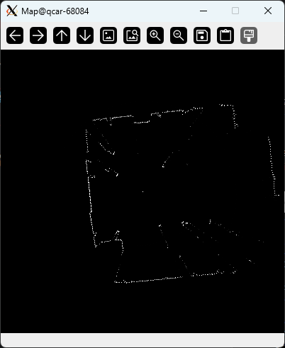
bash
python3 QCar2_lidar_point_cloud.py- A window should open looking similar to:
- Code for
QCar2_lidar_point_cloud.py:
python
## LIDAR_Point_Cloud.py
# This example uses the LiDAR point cloud to construct a temporary local map of the QCar's environment
# To troubleshoot the physical LiDAR use the hardware_test_rp_lidar_a2.py found in the hardware_tests directory

from pal.products.qcar import QCarLidar
from pal.utilities.math import *
import time
import numpy as np
import cv2

# -- -- -- -- -- -- -- -- -- -- -- -- -- -- -- -- -- -- -- -- -- -- -- -- -- -- -- -- -- -- -- -- -- -- -- --
## Timing Parameters and methods
startTime = time.time()
def elapsed_time():
	return time.time() - startTime

sampleRate 	   = 30
sampleTime 	   = 1/sampleRate
simulationTime = 30.0
print('Sample Time: ', sampleTime)

# -- -- -- -- -- -- -- -- -- -- -- -- -- -- -- -- -- -- -- -- -- -- -- -- -- -- -- -- -- -- -- -- -- -- -- --
## Additional parameters and buffers
pixelsPerMeter 	  = 50 # pixels per meter
sideLengthScale = 8 * pixelsPerMeter # 8 meters width, or 400 pixels side length
decay 		      = 0.9 # 90% decay rate on old map data
maxDistance  	  = 3.9
map    		  	  = np.zeros((sideLengthScale, sideLengthScale), dtype=np.float32) # map object


# Lidar settings
numMeasurements 	 = 1000	# Points
lidarMeasurementMode 	 = 2
lidarInterpolationMode = 0

# LIDAR initialization and measurement buffers
myLidar = QCarLidar(
	numMeasurements=numMeasurements,
	rangingDistanceMode=lidarMeasurementMode,
	interpolationMode=lidarInterpolationMode
)


# -- -- -- -- -- -- -- -- -- -- -- -- -- -- -- -- -- -- -- -- -- -- -- -- -- -- -- -- -- -- -- -- -- -- -- --
## Main Loop
try:
	while elapsed_time() < simulationTime:
		# decay existing map
		map = decay*map

		# Start timing this iteration
		start = time.time()

		# Capture LIDAR data
		myLidar.read()

		# convert angles from lidar frame to body frame
		anglesInBodyFrame = myLidar.angles * -1 + np.pi


		# Find the points where it exceed the max distance and drop them off
		idx = [i for i, v in enumerate(myLidar.distances) if v < maxDistance]

		# convert distances and angles to XY contour
		x = myLidar.distances[idx]*np.cos(anglesInBodyFrame[idx])
		y = myLidar.distances[idx]*np.sin(anglesInBodyFrame[idx])

		# convert XY contour to pixels contour and update those pixels in the map
		pX = (sideLengthScale/2 - x*pixelsPerMeter).astype(np.uint16)
		pY = (sideLengthScale/2 - y*pixelsPerMeter).astype(np.uint16)

		map[pX, pY] = 1

		# End timing this iteration
		end = time.time()

		# Calculate the computation time, and the time that the thread should pause/sleep for
		computationTime = end - start
		sleepTime = sampleTime - ( computationTime % sampleTime )

		# Display the map at full resolution
		cv2.imshow('Map', map)

		# Pause/sleep for sleepTime in milliseconds
		msSleepTime = int(1000*sleepTime)
		if msSleepTime <= 0:
			msSleepTime = 1 # this check prevents an indefinite sleep as cv2.waitKey waits indefinitely if input is 0
		cv2.waitKey(msSleepTime)


except KeyboardInterrupt:
	print("User interrupted!")

finally:
	# Terminate the LIDAR object
	myLidar.terminate()
# -- -- -- -- -- -- -- -- -- -- -- -- -- -- -- -- -- -- -- -- -- -- -- -- -- -- -- -- -- -- -- -- -- -- -- --8.5 RGBD Imaging
Documentation QCar2_RGBD Imaging.pdf
- Connect to QCar by either:
- Windows Remote Desktop (window in step 4 will open on QCar 2 desktop)
- Launch
XLaunchon the GCS andputtyto the QCar2 withX11 forwardingenabled (window in step 4 will open on GCS)
- On the QCar 2, change directory to:
bash
cd /home/nvidia/Documents/Quanser/5_research/sdcs/qcar2/hardware/applications/rgbd_imaging- Run:
bash
python3 QCar2_rgbd_imaging.py- On the GCS, a window should open looking similar to:
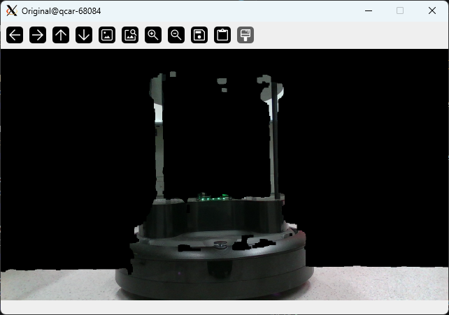
It uses the depth camera to filter out portions of the RGB image which are beyond a programmed distance or below a programmed distance.
- Code for
QCar2_rgbd_imaging.py:
python
## rgbd_imaging.py
# This example combines the depth and RGB sensors from the Intel Realsense D435 to display objects
# within a specified distance. For troubleshooting the Realsense camera use hardware_test_intelrealsense.py
# found in the hardwate_tests folder.

from pal.utilities.vision import Camera3D
from hal.utilities.image_processing import ImageProcessing

import time
import struct
import numpy as np
import cv2

# -- -- -- -- -- -- -- -- -- -- -- -- -- -- -- -- -- -- -- -- -- -- -- -- -- -- -- -- -- -- -- -- -- -- -- --
## Timing Parameters and methods
startTime = time.time()
def elapsed_time():
    return time.time() - startTime

sampleRate     = 30.0
sampleTime     = 1/sampleRate
simulationTime = 30.0
print('Sample Time: ', sampleTime)

# -- -- -- -- -- -- -- -- -- -- -- -- -- -- -- -- -- -- -- -- -- -- -- -- -- -- -- -- -- -- -- -- -- -- -- --
# Additional parameters
imageWidth  = 1280
imageHeight = 720

# -- -- -- -- -- -- -- -- -- -- -- -- -- -- -- -- -- -- -- -- -- -- -- -- -- -- -- -- -- -- -- -- -- -- -- --
## Initialize the RealSense camera for RGB and Depth data
myCam1  = Camera3D(mode='RGB&DEPTH', frameWidthRGB=imageWidth, frameHeightRGB=imageHeight)
# max_distance_view = 5
MAX_DISTANCE = 0.6 # pixels in RGB image farther than this will appear white
MIN_DISTANCE = 0.0001 # pixels in RGB image closer than this will appear black

# -- -- -- -- -- -- -- -- -- -- -- -- -- -- -- -- -- -- -- -- -- -- -- -- -- -- -- -- -- -- -- -- -- -- -- --

## Main Loop
flag = True
try:
    while elapsed_time() < simulationTime:
        # Start timing this iteration
        start = time.time()

        # Read the RGB and Depth data (latter in meters)
        myCam1.read_RGB()
        myCam1.read_depth(dataMode='M')

        # Threshold the depth image based on min and max distance set above, and cast it to uint8 (to be used as a mask later)
        binaryNow = ImageProcessing.binary_thresholding(myCam1.imageBufferDepthM, MIN_DISTANCE, MAX_DISTANCE).astype(np.uint8)

        # Initialize binaryBefore to keep a 1 step time history of the binary to do a temporal difference filter later.
        # At the first time step, flag = True. Initialize binaryBefore and then set flag = False to not do this again.
        if flag:
            binaryBefore = binaryNow
            flag = False

        # clean  =  closing filter applied ON ( binaryNow BITWISE AND ( BITWISE NOT of ( the ABSOLUTE of ( difference between binary now and before ) ) ) )
        binaryClean = ImageProcessing.image_filtering_close(cv2.bitwise_and( cv2.bitwise_not(np.abs(binaryNow - binaryBefore)/255), binaryNow/255 ), dilate=3, erode=1, total=1)

        # grab a smaller chunk of the depth data and scale it back to full resolution to account for field-of-view differences and physical distance between the RGB/Depth cameras.
        binaryClean = cv2.resize(binaryClean[81:618, 108:1132], (1280, 720)).astype(np.uint8)

        # Apply the binaryClean mask to the RGB image captured, and then display it.
        maskedRGB = cv2.bitwise_and(myCam1.imageBufferRGB, myCam1.imageBufferRGB, mask=binaryClean)
        cv2.imshow('Original', cv2.resize(maskedRGB, (640, 360)))

        # End timing this iteration
        end = time.time()

        # Calculate the computation time, and the time that the thread should pause/sleep for
        computationTime = end - start
        sleepTime = sampleTime - ( computationTime % sampleTime )

        # Pause/sleep for sleepTime in milliseconds
        msSleepTime = int(1000*sleepTime)
        if msSleepTime <= 0:
            msSleepTime = 1
        cv2.waitKey(msSleepTime)
        binaryBefore = binaryNow

except KeyboardInterrupt:
    print("User interrupted!")

finally:
    # Terminate RealSense camera object
    myCam1.terminate()
# -- -- -- -- -- -- -- -- -- -- -- -- -- -- -- -- -- -- -- -- -- -- -- -- -- -- -- -- -- -- -- -- -- -- -- --8.6 Yolo
Documentation QCar2_YOLO_object_segmentation.pdf
- Connect to QCar by either:
- Windows Remote Desktop (window in step 4 will open on QCar 2 desktop)
- Launch
XLaunchon the GCS andputtyto the QCar2 withX11 forwardingenabled (window in step 4 will open on GCS)
- On the QCar 2, change directory to:
bash
cd /home/nvidia/Documents/Quanser/5_research/sdcs/qcar2/hardware/applications/yolo- Run:
bash
python3 QCar2_YOLOv8_object_segmentation.pyNote that when running the script for the first time, the QCar 2 needs to be connected to internet, as the trained PyTorch model will be downloaded from host. Then the downloaded model will be converted to a TensorRT engine to improve inference time, which can take up to 20 minutes.
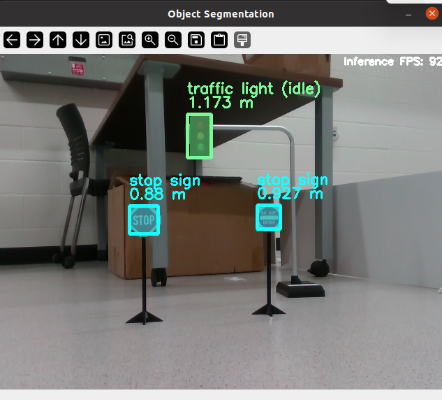
- A window should open looking similar to:
- Code for
QCar2_YOLOv8_object_segmentation.py:
python
import numpy as np
import time
import cv2
from pit.YOLO.nets import YOLOv8
from pit.YOLO.utils import QCar2DepthAligned

## Timing Parameters and methods
def elapsed_time():
    return time.time() - startTime

sampleRate     = 30.0
sampleTime     = 1/sampleRate
simulationTime = 30.0
print('Sample Time: ', sampleTime)

# -- -- -- -- -- -- -- -- -- -- -- -- -- -- -- -- -- -- -- -- -- -- -- -- -- -- -- -- -- -- -- -- -- -- -- --
# Additional parameters
imageWidth  = 640
imageHeight = 480

# -- -- -- -- -- -- -- -- -- -- -- -- -- -- -- -- -- -- -- -- -- -- -- -- -- -- -- -- -- -- -- -- -- -- -- --
# Initialize YOLOv8 segmentation model
myYolo  = YOLOv8(
                 # modelPath = 'path/to/model',
                 imageHeight= imageHeight,
                 imageWidth = imageWidth,
                )

# Initialize Depth/RGB alignment RT model
QCarImg = QCar2DepthAligned()

try:
    startTime = time.time()
    while elapsed_time()<simulationTime:
        start = time.time()

        # Get aligned RGB and Depth images
        QCarImg.read()

        rgbProcessed = myYolo.pre_process(QCarImg.rgb)
        predecion = myYolo.predict(inputImg = rgbProcessed,
                                   classes = [2,9,11],
                                   confidence = 0.3,
                                   half = True,
                                   verbose = False
                                   )

        processedResults=myYolo.post_processing(alignedDepth = QCarImg.depth,
                                                clippingDistance = 5)
        for object in processedResults:
            print(object.__dict__)
        print('---------------------------')

        # annotatedImg=myYolo.render(showFPS = True)
        annotatedImg=myYolo.post_process_render(showFPS = True)
        cv2.imshow('Object Segmentation', annotatedImg)

        # End timing this iteration
        end = time.time()

        # Calculate the computation time, and the time that the thread should pause/sleep for
        computationTime = end - start
        sleepTime = sampleTime - ( computationTime % sampleTime )

        # Pause/sleep for sleepTime in milliseconds
        msSleepTime = int(1000*sleepTime)
        if msSleepTime <= 0:
            msSleepTime = 1
        cv2.waitKey(msSleepTime)

except KeyboardInterrupt:
    print("User interrupted!")

finally:
QCarImg.terminate()8.7 LaneNet
Documentation QCar2_LaneNet_lane_estimation.pdf
- Connect to QCar by either:
- Windows Remote Desktop (window in step 4 will open on QCar 2 desktop)
- Launch
XLaunchon the GCS andputtyto the QCar2 withX11 forwardingenabled (window in step 4 will open on GCS)
- On the QCar 2, change directory to:
bash
cd /home/nvidia/Documents/Quanser/5_research/sdcs/qcar2/hardware/applications/lanenet- Run:
bash
python3 QCar2_LaneNet_lane_estimation.pyNote that when running the script for the first time, the QCar 2 needs to be connected to internet, as the trained PyTorch model will be downloaded from host. Then the downloaded model will be converted to a TensorRT engine to improve inference time, which can take up to 20 minutes.
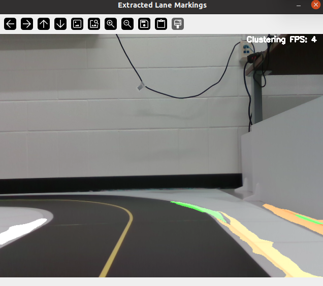
- A window should open looking similar to:
- Code for
QCar2_LaneNet_lane_estimation.py:
python
import numpy as np
import cv2
import time
from pit.LaneNet.nets import LaneNet
from pal.utilities.vision import Camera3D


## Timing Parameters and methods
def elapsed_time():
    return time.time() - startTime

sampleRate     = 30.0
sampleTime     = 1/sampleRate
simulationTime = 30.0
print('Sample Time: ', sampleTime)

# -- -- -- -- -- -- -- -- -- -- -- -- -- -- -- -- -- -- -- -- -- -- -- -- -- -- -- -- -- -- -- -- -- -- -- --
# Additional parameters
imageWidth  = 640
imageHeight = 480

# -- -- -- -- -- -- -- -- -- -- -- -- -- -- -- -- -- -- -- -- -- -- -- -- -- -- -- -- -- -- -- -- -- -- -- --
# Initialize the LaneNet model
myLaneNet = LaneNet(
                    # modelPath = 'path/to/model',
                    imageHeight = imageHeight,
                    imageWidth = imageWidth,
                    rowUpperBound = 240
                    )

# Initialize the RealSense camera for RGB
myCamRGB  = Camera3D(mode='RGB', frameWidthRGB=imageWidth, frameHeightRGB=imageHeight)

try:
    startTime = time.time()
    while elapsed_time()<simulationTime:
        start = time.time()
        # Read the RGB
        myCamRGB.read_RGB()

        rgbProcessed=myLaneNet.pre_process(myCamRGB.imageBufferRGB)
        binaryPred , instancePred = myLaneNet.predict(rgbProcessed)
        isolatedLane = myLaneNet.post_process(eps=0.5,
                                              min_samples=250,
                                              min_area=100)

        # annotatedImg = myLaneNet.render(showFPS = True)
        annotatedImg = myLaneNet.post_process_render(showFPS = True)

        cv2.imshow('Extracted Lane Markings', annotatedImg)

        # End timing this iteration
        end = time.time()

        # Calculate the computation time, and the time that the thread should pause/sleep for
        computationTime = end - start
        sleepTime = sampleTime - ( computationTime % sampleTime )

        # Pause/sleep for sleepTime in milliseconds
        msSleepTime = int(1000*sleepTime)
        if msSleepTime <= 0:
            msSleepTime = 1
        cv2.waitKey(msSleepTime)

except KeyboardInterrupt:
    print("User interrupted!")

finally:
myCamRGB.terminate()9. ROS 2
Documentation ROS 2 QCar2.pdf
Note that the QCar 2 come with ROS 2 humble and is running Ubuntu 20.04 (normally ROS 2 humble runs on Ubuntu 22.04).
9.1 Getting Started
- Copy contents of
ros2\src:
bash
cp -r ~/Documents/Quanser/5_research/sdcs/qcar2/ros2/src/* ~/ros2/srcThree subdirectories should be copied:
- qcar2_autonomy
- qcar2_interfaces
- qcar2_nodes
- Install tools:
bash
sudo apt update
sudo apt install python3-setuptools- Build the ROS 2 packages:
bash
cd ~/ros2
colcon build
9.2 Check ROS 2
- Run the install script:
bash
cd ~/ros2
source install/setup.bash- Launch file to publish all sensor centric nodes:
bash
ros2 launch qcar2_nodes qcar2_launch.py- In another terminal window, start
RViz(after running the install script):
bash
rviz2- In
RViz:
- Set
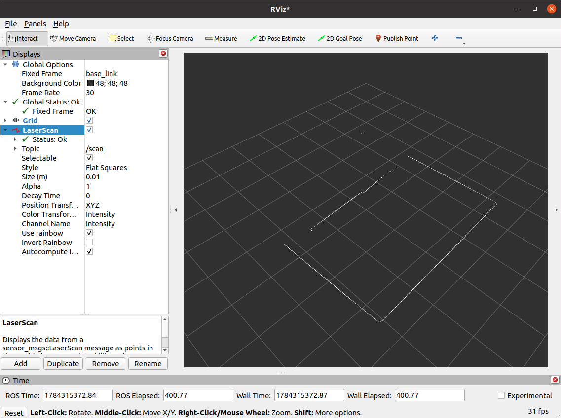
Global Options > Fixed Frametobase_link - Add topic
LaserScan - Set
LaserScan > Topicto/scan
The RViz window should look similar to: